Line Tracking
2023-11-01
Design ideas
AfterCalibration line detection circuit, we can start to make effective use of the Line-Detecting Circuit.
According to the principles described in the Hardware analysis and calibration chapter,line trackingrequires real-time light intensity detection by using the different reflectivity of dark lines and its two sides.
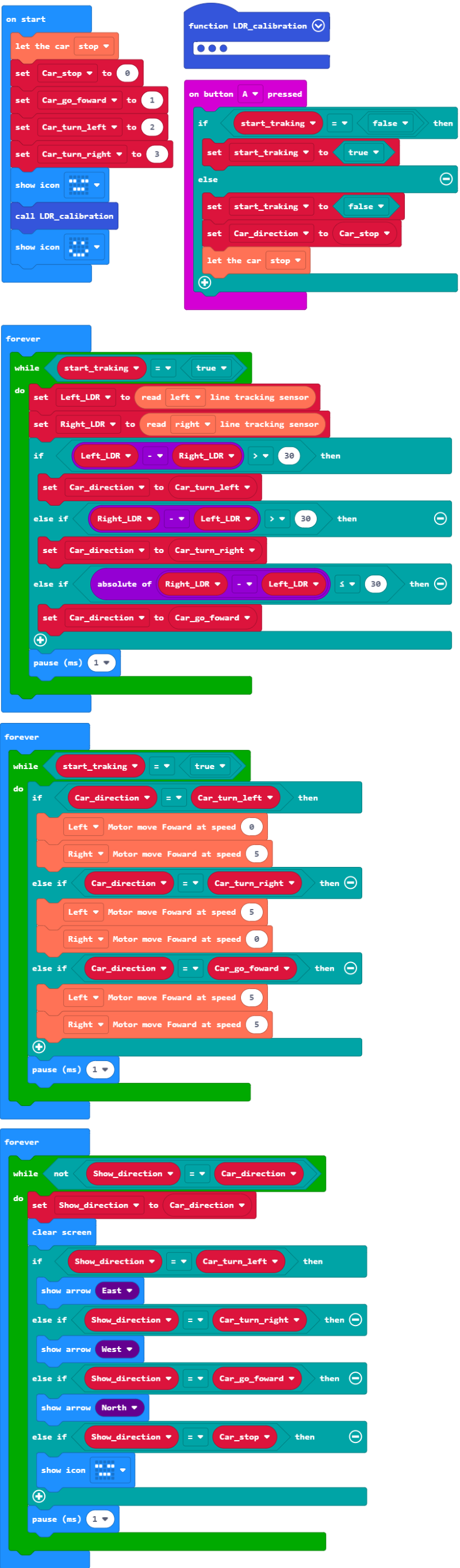
Example Blocks
Example project file on Github
After the project file is downloaded locally, it can be imported into MakeCode for viewing and re-editing, or it can be burned directly to micro:bit via USB to run.
Design description
- The "on button A pressed" block is used to control the start and stop of the tracking program. Each time button A is pressed, the variables set in it will change its state.
- The "forever" block will repeatedly execute its internal program, and each time the loop ends or the "show" or "pause" block is executed in the loop, the thread will allow other "forever" blocks or event-based loops, so this Three "forever" blocks and one "on button A pressed" block can run together in the background, so that the system has the ability to execute multiple programs at the same time. This is generally called "multitasking".
- The program in the first "forever" block is used to cyclically read the voltage analog values of the left and right LDRs, and then judge in the multi-level "if" conditional block, and change the variable when the corresponding conditions are met. The variable is used to control the motor .
- The multi-level "if" condition block in the second "forever" block judges the variable value changed in the first "forever" block, and directly outputs control signals to control the start, stop and speed of the left and right motors.
- First, the loop condition in the two "forever" blocks is the variable controlled by the "on button A pressed" block. The loop will execute only when the variable is "true".
- The third "forever" block is a bit ingenious. Its internal loop will only be executed once when the variable used to control the motor changes, corresponding to the content that the LED should display currently.