【Introduction to development board】
The BPI-PicoW-S3 has an onboard ESP32-S3 chip that supports 2.4 GHz Wi-Fi and Bluetooth® LE dual-mode wireless communication. The board supports two power supply modes: USB and IO power supply, which can realize the function of automatic power switching under dual power supply. Small size, convenient interface, easy to use, and can be directly applied to low-power IoT projects.
The BPI-PicoW-S3 development board supports ESP-IDF, Arduino, MicroPython and other methods for programming and development in terms of software.
All IO pins corresponding to the chip are marked on the BPI-PicoW-S3 development board, and the shape is consistent with the Raspberry Pico W development board. Developers can add peripheral devices supported by the Raspberry Pico W to the BPI-PicoW- On the S3, the development board can also be plugged into the breadboard.
key features
- ESP32-S3, Xtensa® 32 bit LX7
- On-chip peripherals PSRAM, off-chip FLASH
- Ultra-low power 10uA
- 2.4G WIFI, Bluetooth 5, Bluetooth mesh
- GPIO , ADC , TOUCH , PWM , I2C , SPI , RMT , I2S , UART , LCD, CAMERA , USB , JTAG
- 1*MicroUSB
- 1 * Full Color LED
hardware
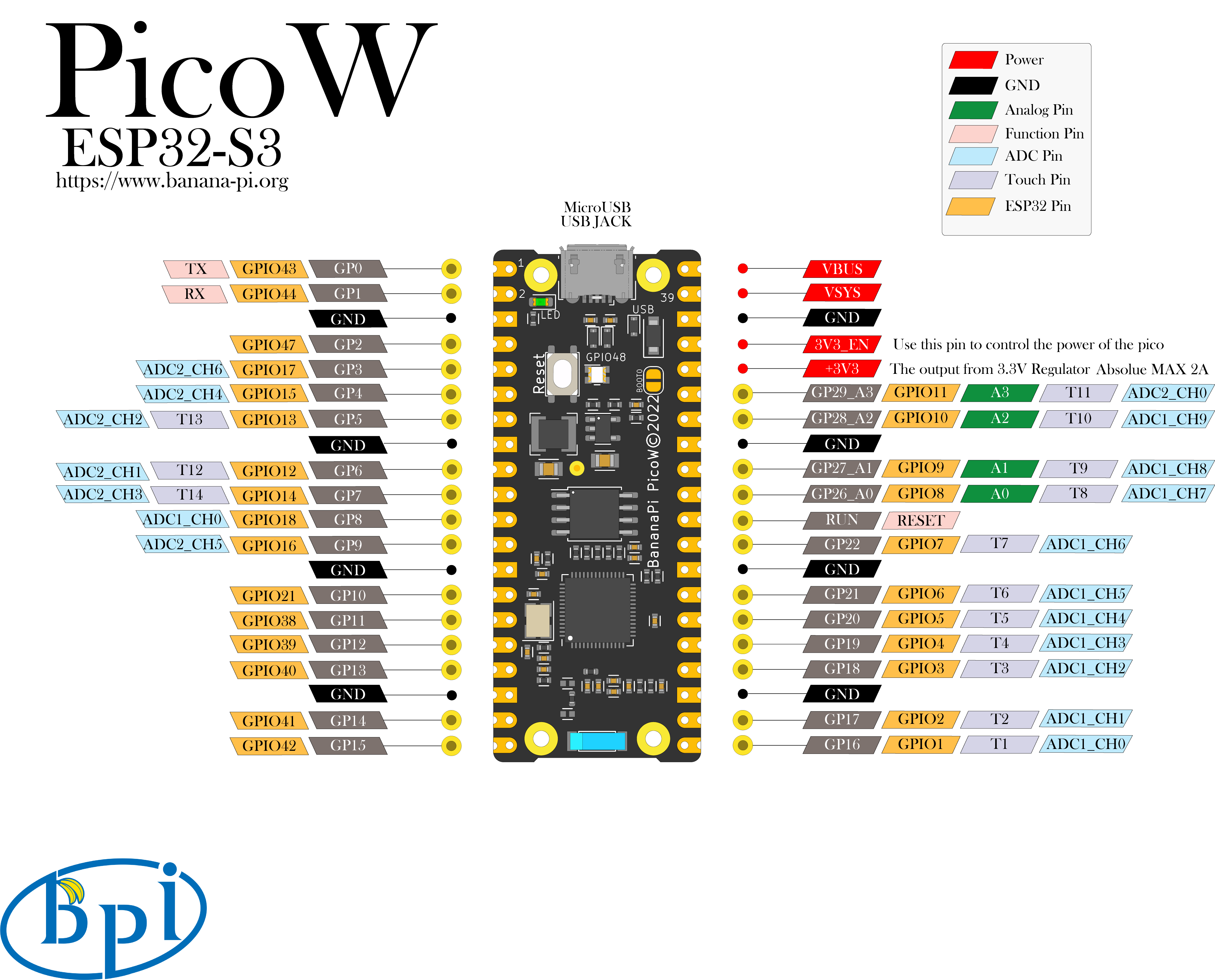
Interface diagram
Hardware Specifications
| BPI-PicoW-S3 Spec Sheet | |
| SoC main control chip | ESP32-S3, Xtensa® 32-bit LX7 Dual-Core Processor |
| Frequency | 240MHz MAX |
| Operating Temperature | -40℃~+85℃ |
| On-Chip ROM | 384KB |
| On-chip SRAM | 320KB |
| Off-chip FLASH ROM | 8MB |
| On-Chip Peripherals PSRAM | 2MB |
| WIFI | IEEE 802.11 b/g/n, 2.4Ghz band, 150Mbps |
| Bluetooth | Bluetooth 5, Bluetooth mesh |
| GPIO | BPI-PicoW-S3 has brought out 27 available GPIOs |
| ADC | 2 × 12-bit SAR ADC supporting 20 analog channel inputs |
| TOUCH Capacitive Touch Sensor | 14 |
| SPI | 4 |
| I2C | 2, supports master or slave mode |
| I2S | 2, serial stereo data input and output |
| LCD | 1, supports 8-bit ~16-bit parallel RGB, I8080, MOTO6800 interface |
| CAMERA | 1, supports 8-bit ~16-bit DVP image sensor interface |
| UART | 3, supports asynchronous communication (RS232 and RS485) and IrDA |
| PWM | 8 independent channels, 14-bit precision |
| MCPWM | 2 |
| USB | 1 × Full Speed USB 2.0 OTG, MicroUSB Female |
| USB Serial/JTAG Controller | 1, USB Full Speed Standard, CDC-ACM, JTAG |
| Temperature Sensor | 1, measuring from –20 °C to 110 °C, for monitoring chip internal temperature |
| SD/MMC | 1 × SDIO host interface with 2 card slots, supports SD card 3.0 and 3.01, SDIO 3.0, CE-ATA 1.1, MMC 4.41, eMMC 4.5 and 4.51 |
| TWAI® Controller | 1, compatible with ISO11898-1 (CAN Specification 2.0) |
| Generic DMA Controller | 5 receive channels and 5 transmit channels |
| RMT | 4 channels transmit, 4 channels receive, shared 384 x 32-bit RAM |
| Pulse Counter | 4 pulse count controllers (units), each with 2 independent channels |
| Timer | 4 × 54-bit general-purpose timers, 16-bit clock prescaler, 1 × 52-bit system timer, 3 × watchdog timers |
| External Crystal | 40Mhz |
| RTC and Low Power Management | Power Management Unit (PMU) + Ultra Low Power Coprocessor (ULP) |
| Low Power Current | 10uA |
| Operating Voltage | 3.3V |
| Input Voltage | 3.3V~5.5V |
| Maximum Discharge Current | 2A@3.3V DC/DC |
| Controllable full color LED | 1 |
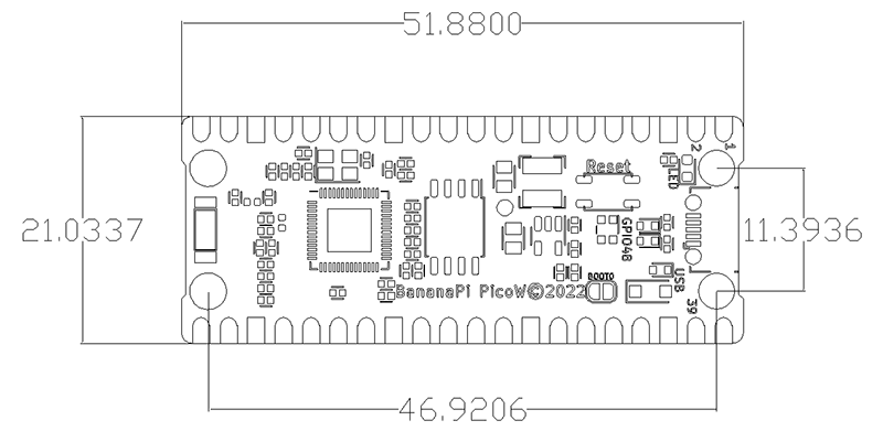
Hardware Dimensions
| BPI-PicoW-S3 Size Chart | |
| Pin spacing | 2.54mm |
| Mounting Hole Spacing | 11.4mm/ 47mm |
| Mounting Hole Dimensions | Inner Diameter 2.1mm/Outer Diameter 3.4mm |
| Motherboard Dimensions | 21 × 51.88(mm)/0.83 x 2.04(inches) |
| plate thickness | 1.2mm |
The pin spacing is compatible with universal boards (hole boards, dot matrix boards), breadboards, and can be directly attached to other PCBs for easy debugging applications.